HOW TO MAKE A LIB PACK WITH 18650 CELLS
The world
is shifting away from fossil fuels and will one day become fully electric.In
the present world ,Lithium-ion is the most promising chemistry of all
batteries. Most of the battery packs used in Laptops,RC Toys, Drones, Medical
devices, Power tools, e-bikes and electric cars (EV) are based on the 18650.It
is one of the most mature Li-ion formats available.
Building a
Li-ion battery pack begins by satisfying voltage and runtime requirements, and
then taking loading, environmental, size and weight limitations into account.
Portable designs for consumer products want a slim profile and the choice is a
prismatic or pouch cell. If space allows, a cylindrical cell such as the 18650
often provides the lowest cost and best performance in terms of specific energy,
safety and durability.
The cylindrical cell is not ideal as it leaves empty spaces in a
multi-cell configuration. This disadvantage turns into an advantage when
considering flexibility and cooling. The Tesla S85 EV uses over 7,000 cells,
switched in parallel to boost the current and in series to increase the
voltage. Should one cell in series open, the total power loss is minimal; if
one in parallel shorts, fuse protection removes this cell from the circuit.
Failing cells can thus be eliminated without bringing the battery down.
Meeting Safety Approvals
Reputable
battery manufacturers do not supply Li-ion cells to uncertified battery
assemblers. This precaution is understandable, considering that Li-ion cells
could be charged and discharged beyond safe limits with inadequate protection
circuits.
Authorizing a battery pack for the commercial market and for air
transport can cost $10,000 to $20,000. Such a high price is troubling, knowing
that cell manufacturers discontinue older cells in favor of higher capacity
replacements. A pack with the new cell, even if specified as a direct
replacement, requires new certifications.
The common question asked is, €œWhy are additional tests needed
when the cells are already approved?€ The simple answer is that cell approvals
cannot be transferred to the pack because regulatory authorities place the
safety confirmation on a finished product and not the components. The completed
battery must be tested and registered to assure correct assembly and compliance
with safety standards.
As part of the test requirements, the finished battery must
undergo electrical and mechanical assessment to meet the Recommendations on the
Transport of Dangerous Goods on lithium-ion batteries for air shipment, rules
set by the United Nations (UN). The UN Transportation Testing (UN/DOT 38.3)
works in conjunction with the Federal Aviation Administration (FAA), the US
Department of Transport (US DOT) and the International Air Transport
Association (IATA)*. The certification applies to primary and secondary
lithium-based cells.
The UN 38.3
test includes:
T1 €“ Altitude Simulation: Low pressure simulates unpressurized
cargo hold at 15,000 meters.
T2 €“
Thermal Test: Temperature extreme by keeping batteries for 6h at -40°C and then
+75°C.
T3 €“ Vibration:
Simulates vibration during transportation at 7Hz to 200Hz for up to 3 hours.
T4 €“ Shock:
Simulates vibration during transportation at given G-forces relating to battery
size.
T5 €“
External Short Circuit: Short circuit with <0.1„¦ at 50°C. Case cannot exceed
170°C.
T6 €“
Impact: >20mm cylindrical cells are impact tested; <20mm cell types are
crush tested.
T7 €“
Overcharge: Charge at twice the recommended current for 24 hours (secondary
batteries only)
T8 €“ Forced
Discharge: Same as T7, forced discharge with primary and secondary cells.
The test batteries must pass the tests without causing harm, but
the packs do not need to function thereafter. The test is strictly for safety
and not consumer endurance. The authorized laboratory needs 24 battery samples
consisting of 12 new packs and 12 specimens that have been cycled 50 times.
IATA wants to ensure that the batteries in question are airworthy and have
field integrity; cycling the packs 50 times before the test satisfies this
requirement.
The high certification cost discourages small manufacturers from
using Li-ion for low-volume products and entrepreneurs may choose nickel-based
systems instead. These batteries do not need to be tested to the level of
lithium-based products for air transport. While reputable companies follow the
instructions, rules are being broken and the penalties are stiff..
Simple
Guidelines for Using Lithium-ion Batteries
€¢Exercise caution when handling and
testing lithium-ion batteries.
€¢ Do not short-circuit, overcharge,
crush, drop, mutilate, penetrate with foreign objects, apply reverse polarity,
expose to high temperature or disassemble packs and cells.
€¢Use only lithium-ion batteries with a
designated protection circuit and approved charger.
€¢ Discontinue using a battery and/or
charger if the pack temperature rises more than 10ºC (18ºF) on a regular
charge.
€¢ The electrolyte is highly flammable
and battery rupture can cause physical injury.
The 18650 (18mm diameter and 65mm length ) battery is a size
classification of lithium-ion batteries. It is the same shape, but a bit larger
than a AA battery. AA batteries by comparison are sometimes called 14500
batteries, because they have a 14mm diameter and 50mm height.
How to make
a 18650 battery pack for applications like : Power Bank, Solar Generator,
e-Bike, Power wall etc. The fundamental is very simple : Just to combined the
number of 18650 cells in series and parallel to make a bigger pack and finally
to ensue safety adding a BMS to it.
Step 1: Parts and Tools
Required
Parts
Required:
1. 18650
Battery
2.
BMS
3. Ni
Strips
4. Battery
Level Indicator
5. Rocker
Switch
6. DC
Jack
7. 18650
Battery Holder
8. 3M x
10mm Screws
Tools Used
1. Spot
Welder
2. 3D
Printer OR Battery Pack Enclosure
2. Wire
Stripper/ Cutter
3. Hot Air
Blower
3.
Multimeter
5. Li Ion Charger or Battery Formation Cycler
Safety
Equipment :
1. Safety
Goggles
2.
Electrical Gloves
Step 2: Selecting the Right 18650 Cells for the Battery Pack

You will find many types of 18650 cells in the
market in the price range $1 to $10, but which are the best? I will highly
recommend to buy 18650 cells from branded companies These cells that have well
documented performance characteristics and excellent quality control. Reputed
brand 18650 cells are generally costly, but if you consider for long time use
then they are worth to have it.
Please Dont
buy any cells with the word FIRE in the name. In reality, these cells are just
factory rejects, purchased by companies and repackaged in their own branded
cover .Many used batteries are re wrapped as new and white-labeled. They sells
the battery by marking capacity up to 5000mAh, but in actual their capacity are
in between 1000 to 2000 mAh. Another major problem with these cheap 18650 cells
are that high risk of explosion when overheated during the charging or
discharging.
Step 3: Choosing the Right Battery Strips

To make the battery pack, you have to to connect the 18650 cells
together by means of Nickel strips or thick wire. Generally Nickel strips are
widely used for this. In general two types of nickel strips are available in
the market : nickel-plated steel strips and pure nickel strips. We would
suggest to go for the pure nickel. It is little bit costlier than the the
nickel plated steel, but it has much lower resistance. Low resistance means,
less heat generation during the charging and discharging, which leads to longer
useful battery life.
Nickel
strips comes with different dimension and length. Choose the strips according
to the current rating.
Step 4: Spot Welding Vs Soldering

You have two options two connect the 18650 cells
together : 1. Soldering 2. Spot Welding
The best
choice is always Spot welding, but Spot Welder is much more costlier than a
good quality Soldering Iron.
Soldering :
You should
know why Spot welding is preferred over soldering, the problem with soldering
is that you apply a lot of heat to the cell and it doesn€™t dissipate very
quickly. This enhance the chemical reaction in the cell which damages the
cell's performance. Ultimately you will loose some capacity and life the cells.
Spot
Welding :
The reason
we spot weld, because it is securely join the cells together without adding
much heat to them.
Step 5: Check the Cell Voltage


Before connecting the cells in parallel, first check the
individual cell voltages.For paralleling the cells,the voltage of each cells
should be near to each other, otherwise a high amount of current will flow from
the cell with higher voltage to the cell with lower voltage.This can damage the
cells and even result in fire on rare occasions.
If you are
using brand new cells, the cell voltage are near 3.5 V to 3.7 V, you can join
them together without worrying much. But if you are going to use old laptop
battery, be sure the cells voltage are nearly same, other wise charge the cells
to the same voltage level by using a good Li Ion Battery Charger.
Step 6: Battery Pack Capacity and Voltage


To make the battery pack, you have to first finalize the nominal
voltage and capacity of the pack.Either it will be in term of Volt , mAh/ Ah or
Wh. You have to connect the cells in parallel to reach the desired capacity
(mAh ) and connect such parallel group in series to achieve the nominal voltage
(Volt ).
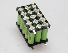
Step 7: Assemble the 18650 Cells

From the previous step, it is clear that our
battery pack is made up of 3 parallel groups connected in series ( 3 x 3.7V =
11.1V ) and each parallel group have 5 cells ( 3400 mAh x 5 = 17000 mAh).Now we
have to arrange the 15 cells properly for making the electrical connection
among them and with the BMS board.
Place the
first parallel group of cells (5 nos) positive side up, then place the second
parallel group negative side up and then finally the last parallel group
positive side up.For better under standing you can see the above picture.
You can
assemble the cells to make the pack by using hot glue or by using plastic 18650
battery holder. We used plastic 18650 cell holders/spacers to assemble the 15
cells. The main advantages of using this cell holders are
1. You can
make the custom pack of any size according to your requirement. It€™s like a
solving a puzzle.
2. It
provide space between the cells, which allow fresh air to pass and the battery
get cooled easily.
3. It makes
your battery pack solid and reliable.
4. It
provide safety anti vibration to your battery pack
Step 8: Spot Weld the Nickel Strips
Now it is time to know the procedure for using the Spot Welder.The
Spot welder have three welding choices: fixed welding head, fixed welding head
with foot switch, movable spot welding pen with foot switch. We prefer to use
the second option.Before welding you have to prepare the nickel strips and
welder.
Cut the
nickel strips :
Lay your
nickel strip on top of the 5 cells ( parallel ), ensuring that it covers all
cells terminals, leave 10mm excess strips for connecting it to the BMS and then
cut it. For series connection cut small nickel strips as shown in the figure.
You will need four long strips for parallel connection and 10 small strips for
series connections.
Connect the
first parallel group negative terminal to the positive terminal of the second
group and then negative terminal of the second group to the positive terminal
of the third group.
Weld the
Battery Strips :
This spot
welder can be used to weld the pure nickel as well as nickel plated steel
strips. You have to adjust the welder pulse and current knob according to the
thickness of the nickel strips.
For 0.15 mm
nickel strips, press the pulse knob 4P and current knob to 4-5.Similarly for
0.2 mm nickel strip , press the pulse knob 4P,6P and current knob to 7-8.Make
sure the welding pen is compressed with the nickel strip and battery terminal,
then press the foot switch.You will notice a small spark, and two dot mark on
the strip.
Successful
Welding :
You can
check the weld quality by pulling on the nickel strip. If it doesn€™t come off
with hand pressure, or requires a lot of strength, then it€™s a good weld. If
you can easily peel it off, then you have to increase the current.
Safety :
Before starting the spot welding, always wear safety goggles.
Step 9: Adding the BMS


A battery management system (BMS) is any
electronic system that manages a a lithium battery pack and the main
functionalities are
1. Monitors
all of the parallel groups in the battery pack and disconnect it from the input
power source when fully charged ( near 4.2V )
2. Balance
all the cells voltage equally
3. Doesn't
allow the the pack from over-discharged.
The two
important parameter required to buy a BMS are : i) Number of cells in series -
like 2S / 3S / 4S
ii).
Maximum discharge Current - like 10A/ 20A /25A /30A
We have
used a 3S and 25A BMS board. These are the specifications of that BMS :
Over
voltage range: 4.25~4.35V ± 0.05V
Over
discharge voltage range: 2.3~3.0V ± 0.05V
Maximum operating current: 0~25
Working
temperature: -40„ƒ ~ +50„ƒ
How to
Connect
Connect the
BMS as shown in the wiring diagram.The BMS have four soldering pads : B- ,B1,B2
and B+.You have to connect the first parallel group negative terminal bus to
the B- and positive terminal bus to the B1. Similarly the third parallel group
negative terminal bus to the B2 and positive terminal bus to the B+.
You can
spot weld the nickel strips to the BMS or solder it to the PCB pad.I preferred
to solder the nickel strips to the PCB for sturdy connection.First apply
soldering flux to the PCB pads and end of the nickel strips.After that tin all
the pads by applying little amount of solder and then solder them together.
Step 10: 3D Printed Enclosure

The battery pack have all around exposed nickel strips, to avoid
any accidental shorting, The enclosure have two parts : Main Body and top lid.
You can get these enclosures from the market or you can make it yourself as per your requirements.
Step 11: Wiring the Components


Normally a standard battery have only two terminal for connecting
the load and to charge the battery.Apart from this, I have added a battery
level indicator, to see the battery level when ever required.I have used a 5mm
DC jack ( 12V /3A ) for input/output , 3S battery level indicator module to see
the battery status and a rocker switch to ON/OFF the battery level indicator.
Now let's
move on to the wiring of the components. I've prepared this simple wiring
diagram for all the components . It's pretty simple!To insulate the conductive
parts, I used heat shrink tubing.
Note :
Don't solder the wires ( P+ and P- ) to the BMS before installing the
components in to the enclosure.
Step 12: Final Assembling


First install the components in to the
respective slots in the 3D printed enclosure. You can see the above picture.
Solder the
positive (red wire ) from the DC jack and Rocker switch to the P+ of the BMS ,
negative wires from the DC jack and Battery level indicator to the P- of BMS.
Then apply
hot glue at the base of the battery compartment, then secure the battery
pack.So that it will seats firmly and prevent any loosing of wire connections.
Finally,
screw the top lids in place! I used 3M x 10 screws for securing the lid. Now
the battery pack is ready to use.
Charging
the Battery Pack :
You can charge the battery pack